
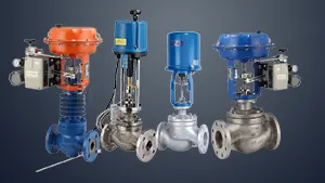
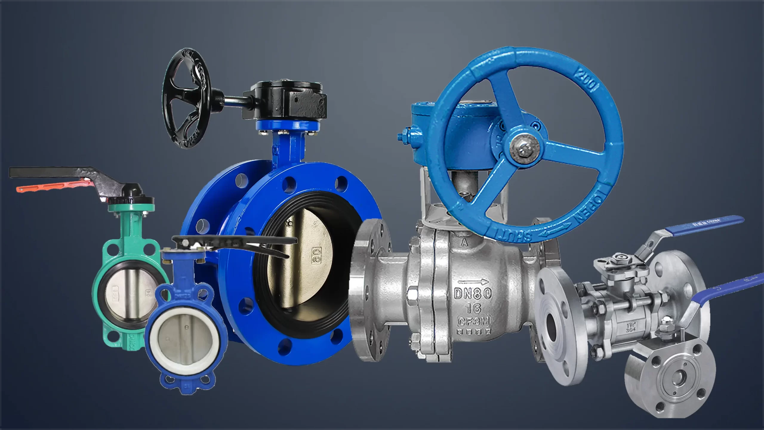
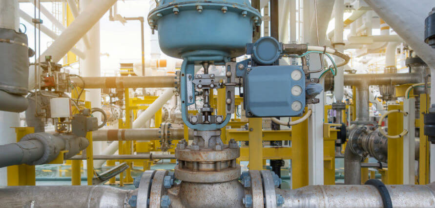
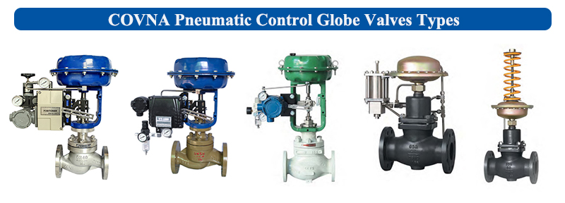
COVNA Pneumatic Globe Control Valve
Pneumatic globe control valve uses compressed gas as the power source and cylinder as the actuator, and drives the valve with the help of accessories such as valve positioner, converter, solenoid valve, retention valve, gas storage tank, gas filter, etc. or proportional adjustment, receiving control signals of industrial automation control system to complete the adjustment of pipeline media: flow, pressure, temperature, liquid level and other process parameters.
The characteristics of the pneumatic control valve are simple control, fast response, and intrinsic safety, no need to take additional explosion-proof measures.
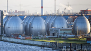
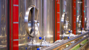
Pneumatic control valve is one of the industrial process control instruments widely used by petroleum, chemical, electric power, metallurgy and other industrial enterprises.
It is usually a combination instrument formed by connecting pneumatic actuator and regulating valve after installation and debugging.
The main advantages of the pneumatic control valve are that the opening and closing speed of the pneumatic control valve is easy to adjust, the structure is simple, and it is easy to maintain. Due to the buffer characteristics of the gas itself during the operation, it is not easy to be damaged due to jamming. It is more reliable than the electric valve in some explosion-proof situations.
The pneumatic control valve also has the function of fault reset. When purchasing, you can choose the air on or off type according to the working condition.
According to the valve action mode can be divided into: straight stroke and angular travel two ways.
Features and applications
- The use and characteristics of pneumatic control valve is a right angle rotary structure, which is used together with the valve positioner to realize proportional adjustment; V-shaped valve core is most suitable for various adjustment occasions, with large rated flow coefficient, large adjustable ratio, good sealing effect, sensitive adjustment performance, small volume, and vertical horizontal installation. It is suitable for controlling gas, steam, liquid and other media.
- Features: it is a right angle rotary structure, which is composed of V-shaped valve body, pneumatic actuator, positioner and other accessories; it has an approximate equal ratio of natural flow characteristics; it adopts double bearing structure, with small starting torque, good sensitivity and induction speed; super cutting ability.
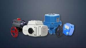
- The pneumatic piston actuator uses compressed air as the power source and drives the crank arm to rotate 90 degrees through the movement of the piston, so as to make the valve open and close automatically. Its components are: adjusting bolt, actuator box, crank arm, cylinder block, cylinder shaft, piston, connecting rod, universal shaft.
- Working principle of pneumatic control valve: pneumatic control valve is composed of actuator and regulating mechanism. The actuator is the thrust component of the control valve. It generates the corresponding thrust according to the control signal pressure to push the regulating mechanism to move. The valve body is the regulating part of the pneumatic control valve. It directly contacts with the regulating medium to regulate the flow of the fluid
- It has the advantages of simple control, fast reaction and intrinsic safety, and no need to take additional explosion-proof measures. Pneumatic control valve is driven by compressed air to realize on-off or proportional regulation. The source is cylinder, which receives control signals from industrial automation control system to adjust various process parameters such as flow, pressure and temperature of pipeline medium.
Installation principle
(1) The installation position of the pneumatic control valve should be at a certain height from the ground, and there should be a certain space at the top and bottom of the valve to facilitate the disassembly and repair of the valve. For the control valve equipped with pneumatic valve positioner and hand wheel, it must be easy to operate, observe and adjust.
(2) The control valve should be installed on the horizontal pipeline and vertical to the pipeline. Generally, it should be supported under the valve to ensure stability and reliability. For special occasions, when the control valve needs to be horizontally installed on the vertical pipeline, the control valve should also be supported (except for small diameter control valve). During installation, additional stress should be avoided to the control valve).
(3) The working environment temperature of the control valve should be between – 30 and + 60, and the relative humidity should not be greater than 95%.
(4) There should be straight pipe section at the front and back of the control valve, and the length should not be less than 10 times of the pipe diameter (10d), so as to avoid the influence of the straight pipe section of the valve on the flow characteristics.
(5) When the diameter of the regulating valve is different from that of the process pipe, the reducing pipe should be used for connection. When the small diameter regulating valve is installed, it can be connected by thread. The flow direction arrow on the valve body should be consistent with the fluid direction.
(6) Bypass piping is to be provided. The purpose is to facilitate switching or manual operation, and the control valve can be overhauled without shutdown.
(7) Before the installation of the control valve, the foreign matters in the pipeline, such as dirt and welding slag, should be completely removed
Precautions for use
1. The valve should be stored in a dry room, both ends of the passage must be blocked. No stacking.
2. The control valve stored for a long time should be inspected regularly to remove the dirt, and anti rust oil should be applied on each moving part and processing surface to prevent rust.
3. The valve should be installed on the horizontal pipeline, and vertical installation is required. Stem up.
4. It is required to install according to the direction of medium flow indicated by the arrow in the figure.
COVNA group aims to provide our customers the best quality products with the most competitive pricing, on-time delivery and full warranty service.
Tags: globe control valve
--- END ---
